ESP8266 is a low cost wi-fi module with full TCP/IP stack produced by manufacturer Espressif .They produce more models which defers only from its I/O pins.
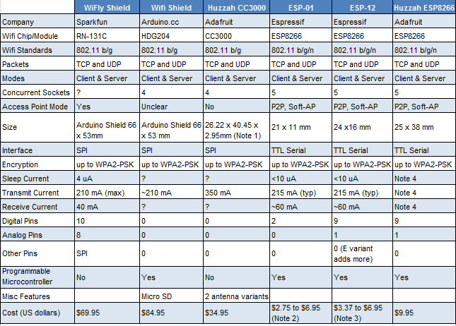
A new Wi-Fi module captured the spotlight of th hobbyists, ESP 8266-E01 module includes a built-in 802.11 b/g/n Wi-Fi circuit that is ready to be directly connected to an antenna. which is priced about 250₹-350₹ (4$-5$).
A picture of ESP8266-E01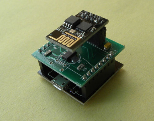
These modules are available in eBay, Amazon. I bought the module from eBay India .If you need you make a purchase from these seller too.
ESP01 is a Wi-Fi module based on popular ESP8266. It is the most convenient wi-fi module for your IoT projects. It can be used with Arduino for Wi-Fi connectivity.
Pin outs of module
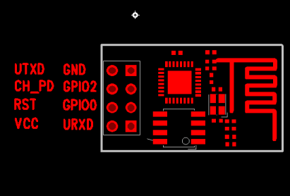
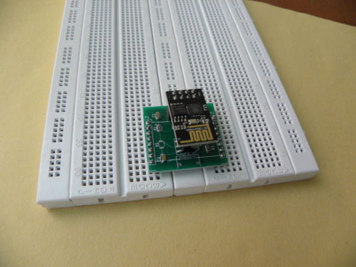
It doesn’t have any voltage regulator and it operates only in 3.3v input.It uses TTL serial interface.And also it can’t be used directly in bread board. It requires a bread board adapter.You can buy that from eBay store also.Check the given links .
2.ESP-01 Bread board adapter/USB TTL Chip
PROGRAMMING THE ESP-01
From the supplier, many (maybe all) of the ESP8266 modules are loaded with “AT” firmware, and can be programmed via a simple terminal program. If you are using the module primarily to exploit its Wi-Fi capabilities and controlling it with another micro controller, this could be all you need.
A more sophisticated option is available from NodeLua, which offers open source firmware based on the Lua programming language. NodeLua is still in development, but already contains extensive capabilities. Other choices include Python, BASIC, and the Arduino IDE, which is featured in this article.
UPDATING THE FIRMWARE
Most of the retailers sell the chip without upgrading the firmware version. By updating the firmware, you can work without any doubt and can focus on your IOT project instead of “guessing and hoping” about the ESP firmware and AT commands. GPIO0 should be kept low during firmware update. There are many websites about flashing firmware, to avoid confusions and external connections(resistors to down the 5v to 3.3v,TTL serial connection) better buy the ESP-01 Bread board adapter/USB TTL Chip which includes inbuilt voltage regulator and TTL serial connections.
Picture of ESP-01 Bread board adapter/USB TTL Chip
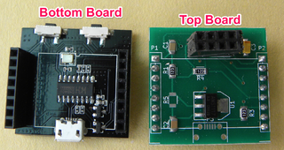
The simplest way to flash firmware is connect the bottom board(which have USB connector and CH430G USB TTL chip. It bridges USB to UART/SPI. This allows your Windows/Mac/Linux PC/Laptop box to communicate to the ESP-01 via USB) with top board. The top board have 8 female header pins.
1.Connect the bottom board,top board and ESP 01.By stacking this three components you get the complete development environment. Now it is similar with other development boards like NodeMCU, D1 Mini or Witty.
2.Connect the stacked board with PC.
3.The designers of ESP8266,Espressif developed a flashing software for their chips. You can download their tools from their official link . (about 5.24mb ) Download,extract,install on your PC.
4.Run ‘ESP_DOWNLOAD_TOOL_V2.4’ after extracting,two windows will appear one looks alike terminal window and one is GUI window.
5.You have to choose the .bin files and to mention the address in order to upgrade successfully .
6.Espressif has a discussion page,where they post their latest firmware (here),under Downloads,click SDK’s ,under Announcements , click [LATEST RELEASE] ESP8266 SDK
{DOWNLOADS->SDK’s->ANNOUNCEMENTS->[LATEST RELEASE] ESP8266 SDK}
OR CLICK HERE
7.Download Non-OS SDK (Latest Version 1.5.4):Release Date :May,20 2016. Click here to download directly from the official site. Go-to the attachments at the mid of the page and click “ESP8266_NONOS_SDK_V1.5.4_16_05_20.zip “or directly click here .
8.You are halfway through the firmware flash.
INSTALLING THE FIRMWARE
9.Run the ESP flash download tool and make sure that none of the boxes at the top left of the GUI window are checked. Enter the COM port you are using, and a baud rate of 115200 in the boxes near the bottom of the window.
10.Connect your stacked board(bottom board,top board,ESP8266-E01). Press and hold the Reset button, and then press and hold the Flash button. Release the Reset button, and then release the Flash button.Click the START button in the flash download tool GUI window.
12.The board detects the info of the board and displays in DETECTED INFO
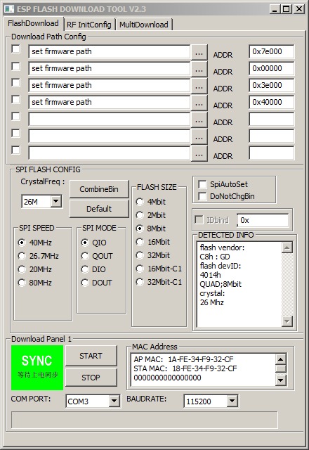
13.Now the GUI obtains information about chip including the size of the flash memory (8Mbit in the example,) the crystal frequency (26MHz in the example,) and two MAC addresses for the chip.
14.Next, click the box in the GUI window labeled “SpiAutoSet,” which will cause the download tool to automatically select the correct flash size and crystal frequency.
15.Now, you need to select the files to be installed in the ESP8266 and set the starting memory address for each file. There are four files that must be correctly installed in order to update the ESP chip. Open the Espressif IOT SDK User Manual and find the section on writing images into flash. In version 1.4 of the manual, it begins on page 20. Next, locate the part that describes the version that supports Cloud Update (FOTA,) and within that part, find the table that pertains to the flash size in your ESP8266.
16.In the example, the flash size is 8Mbits which is equal to 1024KB, so table 2 on page 25 of the manual provides the information needed for the example. See the picture below.
.PNG)
The four files needed are: esp_init_data_default.bin, blank.bin, boot.bin, and a user1.bin file. The address at which each file is to be installed is shown next to the file name. The first three of the required files are located in the esp_iot_sdk_v1.4.1_15_10_22 folder you previously downloaded from bbs.espressif.com, and the fourth is located in the AT_v0.50 bin files. Navigate to where those downloaded files are, and copy each one into one of the blanks at the top of the Flash Download Tool GUI window; enter the correct address for each file in the blank next to the file name. Follow these steps for each file.
- Click inside a file “set firmware path” space.
- Click the … button to the right of the space.
- Navigate to the location of the desired file and click the file. The GUI will automatically enter the file name in the space.
- Enter the correct address (from the table) for each file.
Note that the files to be flashed may not be exactly the same as those listed in the table, but will be a close variant. With a little examination and applied logic, the correct files should be readily apparent.
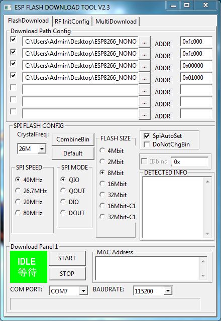
Now, click the four check boxes to the left of each file name. The Flash Download Tool GUI window should be similar to the picture below. Double check the addresses against the table.
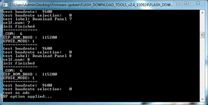
17. On your ESP programming setup, press and hold the Reset button, and then press and hold the Flash button. Release the Reset button, and then release the Flash button. Click the START button in the Flash Download Tool GUI window. The download should begin, and its progress should be shown in the Flash Download Tool GUI window and the log window, as depicted below.
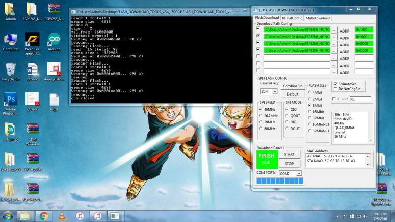
As shown above, a successful flash operation will result in all the files being sent to the ESP8266, and the COM port closed.
You successfully upgraded the firmware.!!
18.Checking the firmware update.
Using AT commands
type AT+GMR and press enter.
your SDK version,AT version will be displayed.

One thought on “ESP 8266 E01 WiFi Module”